|
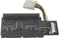
SC-4000 DLT to SCSI tape drive connector
The Problem:
You have a host computer with a
single-ended SCSI port and you want to connect it to a DLT 4000
tape drive that is differential SCSI. So how can you easily
accomplish this?
The Answer:
The SC-4000
Single-Ended/Differential SCSI Converter from MP Tapes.

Quick Reference
Guide
1. Connectors
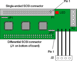
There are two SCSI connectors
on the converter board. P1, mounted on the top of the board, is the
single-ended SCSI bus connector. J1, on the bottom of the board, is
the differential SCSI connector. P1 is configured to accept a
standard single-ended SCSI 50-pin ribbon-cable connector while J1 is
configured to be plugged directly into a differential SCSI device in
place of a cable. Both connectors are 50-pins with 0.1-inch
spacing.
There are two power connectors. P2 accepts a
standard nylon 4-pin power connector in common use for disk and tape
drives. J2 is a “pigtail” connector that plugs into a standard power
connector.
The intended standard installation of the
converter board will be to plug J1 directly into a differential SCSI
device (disk or tape drive), and plug a single-ended SCSI cable into
P1. Power will come from the power supply to the converter via P2,
and J2 will be used to transmit power to the disk or tape drive.
Other installation configurations are possible by the use of cable
adapters and sex-changers.
2. Jumpers
There are two jumpers on the
board. JP1 controls the terminators for the
single-ended SCSI bus. A jumper placed across pin positions 1 and 2
will enable termination, and a jumper across pins 2 and 3 will
remove termination. If no jumper is present, termination is
enabled.
JP2 controls the terminators for the
differential SCSI bus. A jumper placed across pin positions 1 and 2
will enable termination, and a jumper across pins 2 and 3 will
remove termination. If no jumper is present, termination is
enabled.
Note: JP3 is a connector used only during
manufacturing and testing of the board.
3. LED
The red LED will come on when a SCSI
cable is plugged in backwards, or when a single-ended cable is
plugged into the differential socket or vice versa. It may also
light when there is a major problem with the SCSI cabling or
termination anywhere in the system. Whenever the LED is on
continuously, the SCSI converter is disabled to prevent
damage.
The LED will also flash briefly whenever any
SCSI device performs a bus reset. If the light flashes frequently,
it may indicate a cable or system problem.

DLT is a trademark of Quantum
Corp.
| 


